This is the process of numerically modelling fluid flow through the various reservoirs. Sigra’s work covers both predictive modelling and modelling to derive reservoir parameters from real data.
Sigra’s specialist work in determining the reservoir parameters of coal seams is reflected in its numerical models.
In the area of groundwater Sigra has developed a model to determine net inflow and outflow areas from an aquifer subject to recharge.
Stress Path With Fluid Removal
The state of effective stress within a reservoir is extremely important if the permeability of the formation is stress sensitive. Generally the lower the permeability of the formation the more sensitive to effective stress changes it is.
This is particularly the case for coals where an increase in effective stress of 3 MPa (435 psi) may lead to an order of magnitude drop in permeability.
Fluid withdrawal from the reservoir leads immediately to an increase in effective stress. In the case of coals and other carbonaceous reservoir rocks another effect takes place. When gas desorbs from the coal it tends to shrink, which leads to a stress reduction. The two effects oppose each other.
The stress path is the term used to describe the changes in effective stress with fluid withdrawal.
Sigra models the stress path using as inputs:
- Initial Stress Measurement from
- Tectonic strain determination from field measurements of stress + Young’s modulus + Poisson’s ratio
- Hydrofracture field measurements
- Mechanical Properties
- Young’s modulus versus effective stress characteristic
- Poisson’s ratio
- Shrinkage with gas desorption
- Absorption Behaviour
- Reservoir pressure
- Gas sorption pressure/gas content
- Sorption isotherm
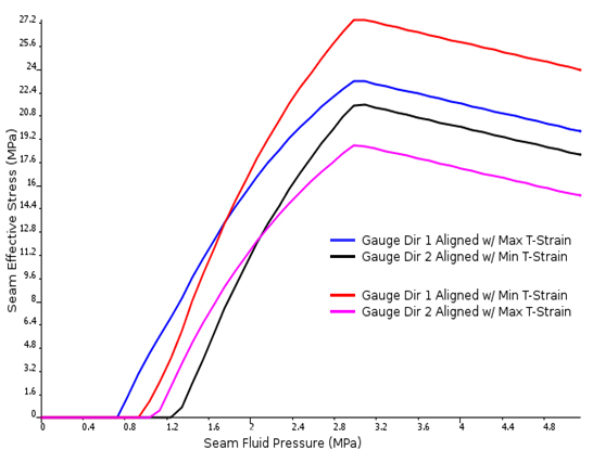
Using this information Sigra creates plots of the effective stress change that may be expected with fluid pressure reduction. An example of such a plot is given in the Figure 1. below.
Coal Seam Reservoir
Models
Sigra can model the behaviour of coal seam reservoirs using two kinds of model.
The first is SIMED, which is an industry accepted finite difference model that is maintained by CSIRO. Whilst this can handle quite complex reservoirs, its use of time delay (tau) to simulate desorption, and limited models to handle the effects of changing effective stress (stress path), mean that it is not as flexible to use as Sigra’s own finite element reservoir model behaviour. This model may be used for simple geometries and in particular for the near well bore area. It handles the stress path related permeability more accurately and directly.
Groundwater Models
Sigra uses a variety of models for groundwater purposes. These include industry standard packages such as MODFLOW, and its own special programs. Three of these are worthy of particular attention.
The first is designed to deal with two phase flow as occurs in unsaturated soils. It uses information on the capillary pressure and changes in atmospheric pressure to model the movement of water in the vadose zone.
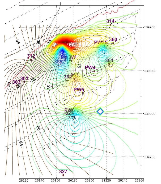
The second model uses real piezometric data, combined with a knowledge of permeability and storage behaviour gained from field testing, to determine the net inflow or outflow from various zones of the model. It has been used to determine the infiltration and groundwater loss from large slope failure models so that suitable drainage designs can be arrived at, to reduce pore pressures and arrest the slope movement. Figure 1 shows such an application.
The third model is for the design of horizontal drains on a slope. It enables the drain spacing to be determined based on a wetted thickness upstream of the drains and the desired wetted thickness downstream. It assumes an impermeable bedrock layer at the base of the slope.