In un-fractured homogeneous rock, the fracture can only start in the axis of the hole. If the borehole axis is not in the plane of the minimum principal stress, the fracture will rotate to be perpendicular to it. When the fracture has extended, pumping is stopped and the fracture is allowed to close through fluid leak off into the rock mass. After closure, the pressure will still decline, and this decline may be used to determine the permeability of the rock mass. The straddled zone in the hole may then be pressurised again to re-open the fracture.
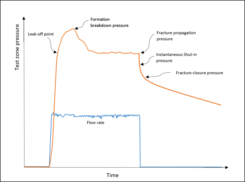
A typical single hydrofracture cycle is shown in Figure 1. Figure 2 shows a graphical method used to determine fracture closure.
The two pressures that are used in the stress analysis of hydrofracture are:
If the fracture is planar and passes through the axis of the borehole, the determination of the fracture closure pressure is straightforward. If the fracture rotates then multiple apparent closure pressures are likely to exist. This is also the case if the hydrofracture extends into a natural fracture which captures it. This complicates analysis and causes uncertainty.
The determination of the major stress from hydrofracture is based on the assumption that the borehole passes through the intersection of the planes of major and minor stress in the rock mass. It also requires the assumption that the rock is linearly elastic. These assumptions are seldom justified and generally the major stress cannot be reliably determined by hydrofracturing.
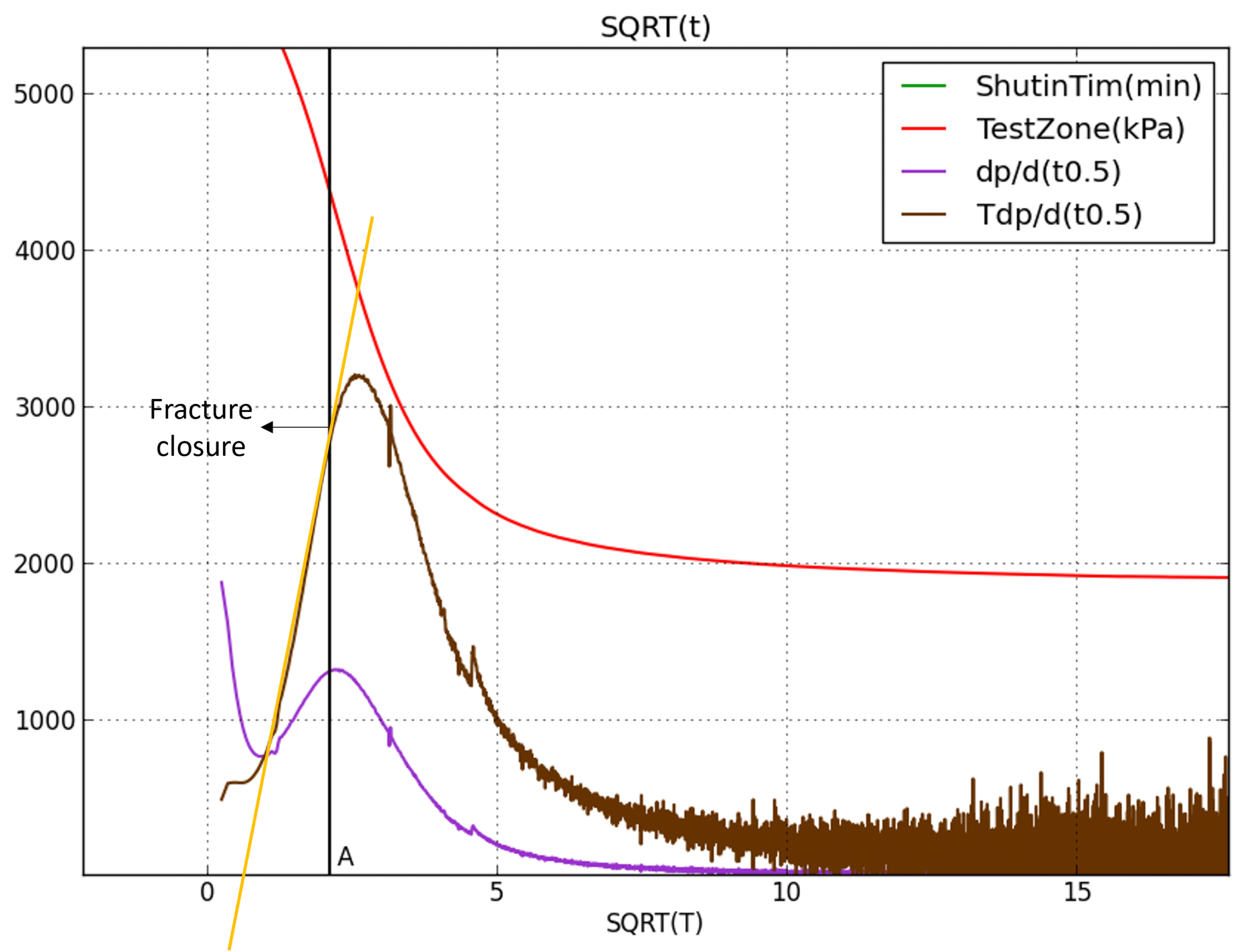
The measurement of permeability from pressure decline after fracture closure is dependent on the time period being examined. In the short term the pressure decline is dominated by linear flow from the fracture. This is dependent on the fracture area, which is generally unknown, making definitive analysis of permeability impossible. In the longer term the pressure response is controlled more by radial flow and a permeability may be more reliably determined. This means that it is necessary to wait long enough after fracture closure if permeability measurement is required.
The use of inflatable packers to seal the hole has complications as it requires the sealing pressure of the packer on the borehole wall to exceed the fluid pressure in the test zone so as to avoid leakage around the packer. By definition the fracture will therefore be initiated by the packer. This effect can be minimised by keeping the packer scaling pressure just above the test zone pressure. This effect can be avoided by cementing a test pipe above a temporary seal in a borehole and fracturing through this. This however makes the subsequent measurement of fracture orientation practically impossible.
Another practical problem associated with hydrofracture is the pressure required to fracture it. Any system will, for hydrofracturing, need to have a pressure capability of 2.5 times the expected mean stress plus the tensile strength of the rock. If that stress is 60 MPa this means having about 170 MPa available. This is beyond the capacity of most packer systems and requires very high pressure pumps.
While most hydrofracture analysis is based on a constant rate injection this is seldom the case. Pressure builds up in the test zone and then the fracture opens with a sudden increase in flow. This flow increase is a better marker of fracture opening than a pressure rise rate change within the test zone.
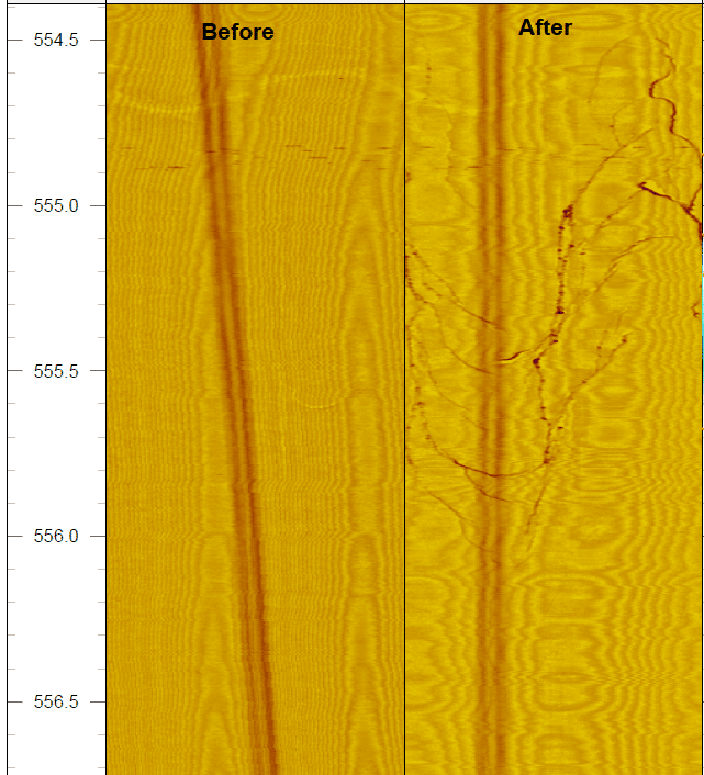
If any stress orientation is required the fracture orientation at the borehole wall must be determined. It is usual practice to use an acoustic televiewer to check the test zone for the absence of fractures prior to testing and for fractures after testing. These are not always clearly visible. In the absence of an acoustic or optical televiewer the core can be examined so that pre-existing joints may be detected and avoided. An impression packer may be used after the test to detect the orientation of any fracture that is generated.
Sigra’s hydrofracture and hydrojacking tools
Sigra has a hydrofracture and hydrojacking system that maintains the packer pressure just above that required to prevent leakage around the packers. This minimises the likelihood of fracture initiation by the packers. This is a very important feature that is lacking in most hydrofracture systems. The Sigra system also uses flow change on hole pressurisation to detect the fracture opening pressure.
The current system is set up for operation with HRQ drill pipe for lower pressures (30 MPa with Sigra rod seals) or with CHD 76 drill pipe for pressures up to 40 MPa. Sigra has a diesel driven frac pump which will produce 40 MPa at a flow rate of 25 litres/minute.


