Sigra became involved in this process as an instrumentation supplier in 2010 and then expanded to become an installation provider because various clients had indicated that improvement was needed in current installation practices.
Sigra has addressed the key issues which are:
Sigra provides a total installation and data acquisition service.
In addition to deep installations Sigra has installation systems for shallow piezometers.
Fully Cement Grouted Piezometers
The most common way to install pressure transducers into a borehole is by cementing them in place. This procedure relies on the cement grout having the correct properties so that hydrofracture of the hole due to excessive fluid pressure does not occur during grouting. It also has to provide adequate fluid connection between the pressure transducer and the formation, but without vertical communication. These provisions place opposing requirements on the cement grout.
Sigra has developed its own specialist cement grouts and procedures to undertake reliable installations provided there is adequate knowledge of the conditions in the hole into which the transducers are being installed. Sigra can generally obtain this information from drilling and geophysical logging and, if available, from its own stress testing. Where there is inadequate information there is always a risk of complications during installation.
To overcome problems with hydrofracture Sigra can choose to cement grout in more than one stage, allowing the cement to substantially set between levels. This is accomplished by the use of a stage grouting valve that allows a port to be opened at a predetermined level in the grout pipe to permit cementing above this level. Alternatively, second level cementing may be accomplished by a secondary grout pipe.
Cement Displacement to Control Communication between the Piezometer and the Formation
Setting piezometers in grout restricts the fluid path between the piezometer and the fluid in the formation. This restriction can become extreme in cases where the formation has low permeability or where the cement grout becomes compacted due to fluid loss into the surrounding ground. The result is that recovery to formation pressure following grouting may become excessively slow, possibly taking months. To overcome this, Sigra has introduced the process of cement displacement.
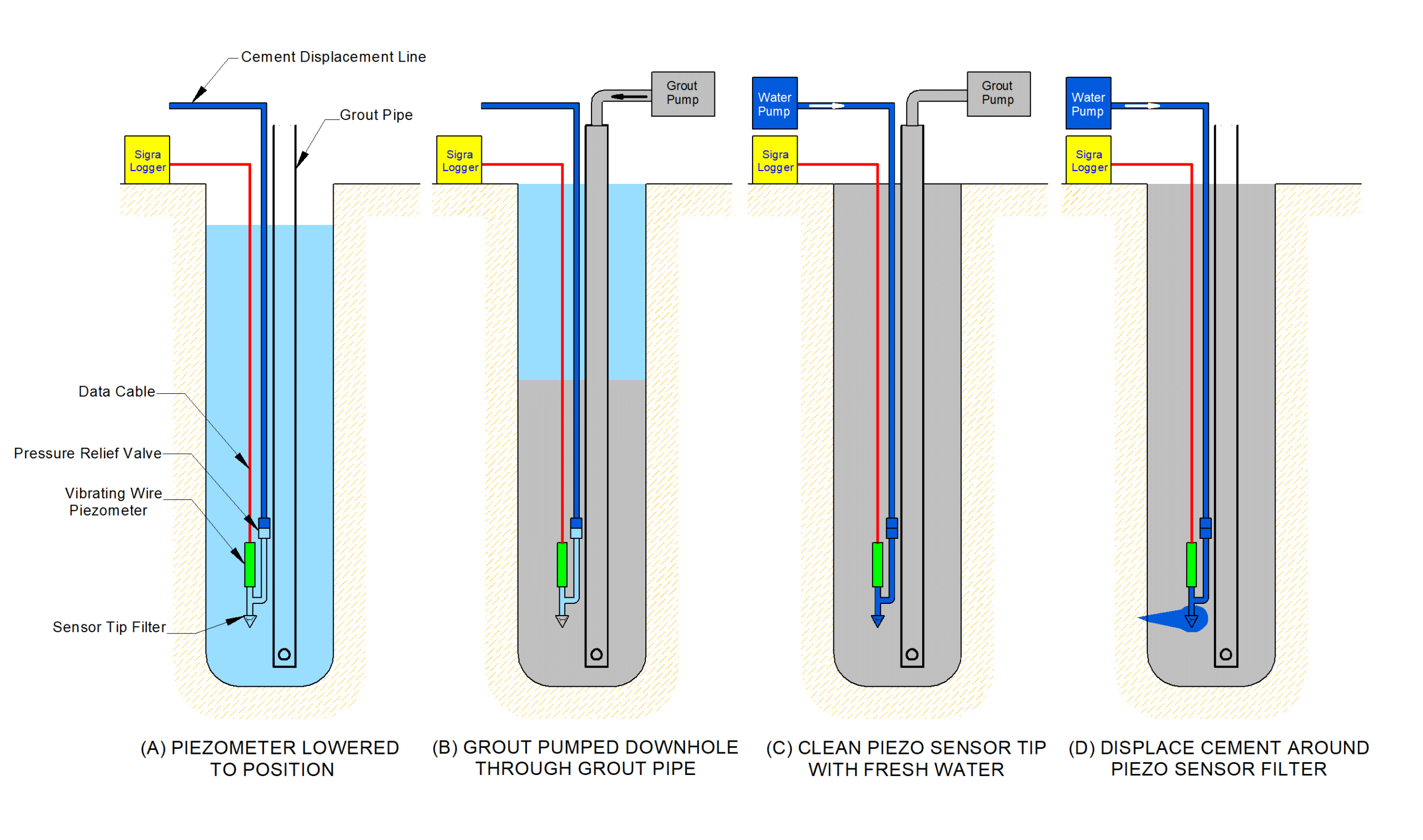
In this, a small diameter fluid line is installed down the borehole to the piezometer and the cement grout displaced from around the piezometer sensor tip by water as setting of the cement grout takes place. The piezometer is isolated from the fluid head in the fluid line by a pressure relief valve.
Figure 1 shows schematically the installation of a single transducer in a borehole using cement displacement. In (A) the piezometer is in position connected electrically to surface by a data cable as well as a cement displacement tube connected to the pressure relief valve and the piezometer. In (B) the system is being grouted. In (C) the filter is cleaned and in (D), when the cement grout has become stiff, but still plastic, the grout is displaced from around the sensor tip.
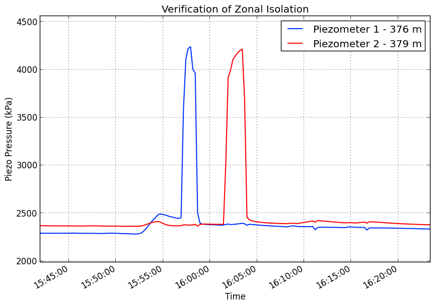
The installation of the cement displacement line provides two additional advantages. Firstly, fluid connection between the piezometer and the formation can be tested, and secondly the degree of vertical fluid connection between multiple piezometers in the borehole can be tested. Both tests are achieved by pumping high pressure water down the fluid line and observing the pressure recovery plot on each piezometer. Figure 2 shows the pressure vs time plot for two fully grouted piezometers spaced only 3 m apart monitoring two separate formations. The steep decline and quick recovery in piezometer pressure after each fluid line is pressurised indicates excellent connectivity to the formation. The lack of a pressure change response in piezometer 1 as piezometer 2 is pressurised and vice versa indicates successful vertical isolation between piezometers.
Piezometer Installation Techniques
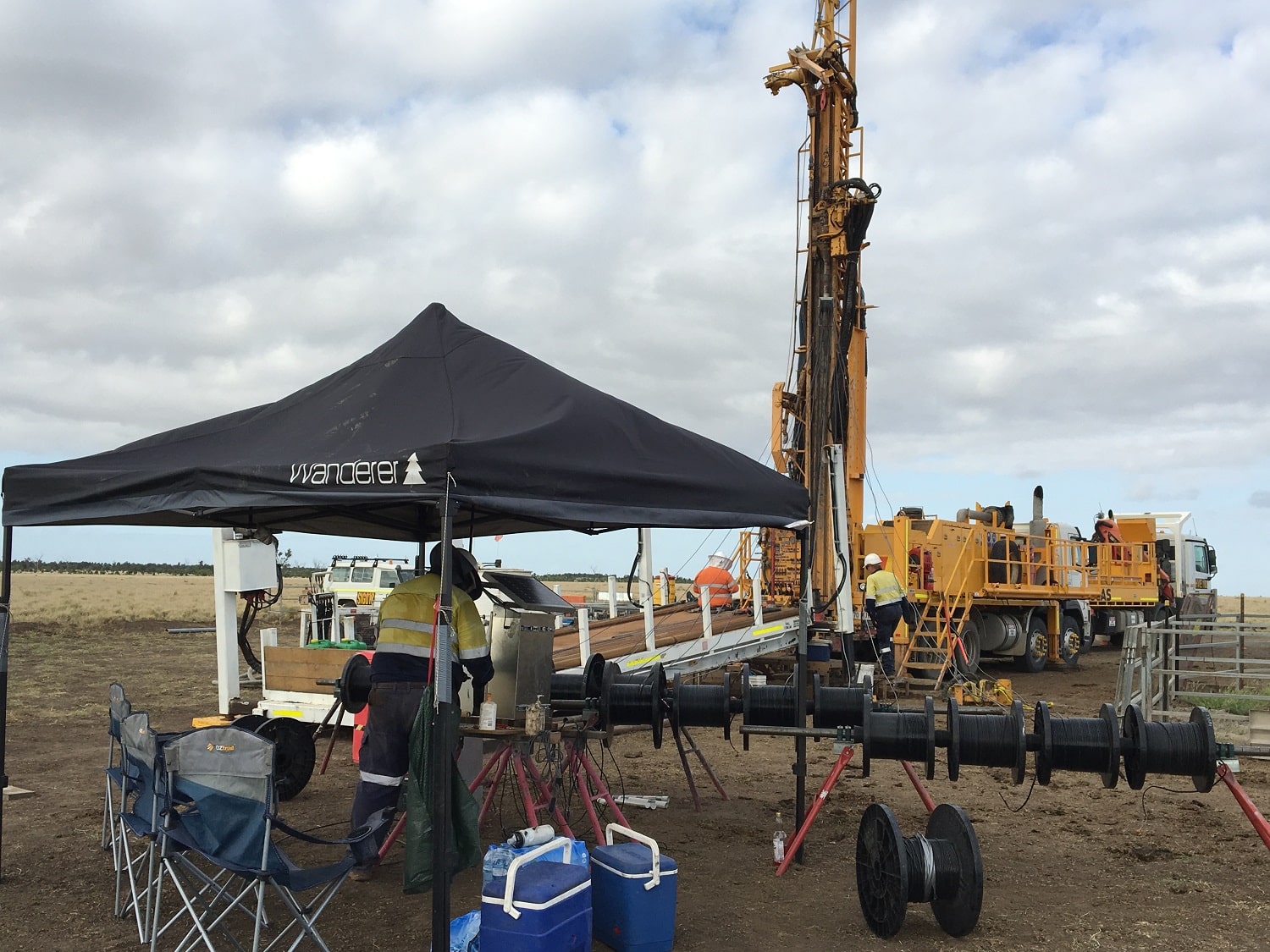
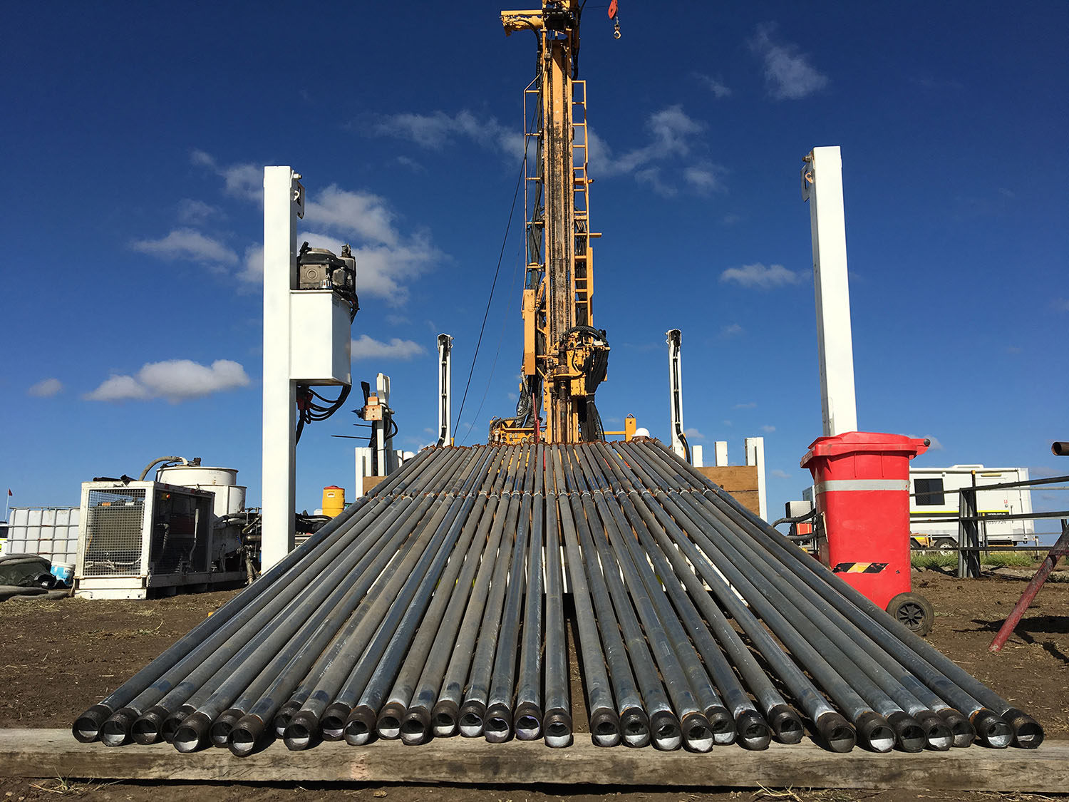
One of the greatest sources of installation problems is an unstable or uneven well bore, especially if it contains ledges. These pose great mechanical load on the assembly being lowered into the borehole and may prevent its installation. To overcome this, Sigra recommends installation through HRQ or HQ drill pipe. This is then withdrawn over the piezometer string and lifted to correct depth prior to cementing. This process is regularly undertaken with piezometer strings at 600m depth. Piezometers may be installed in deeper holes using this technique with different grout strings or by using a heavy mud to maintain hole stability. A cemented piezometer installation operation is shown in Figure 3.
Grout Strings
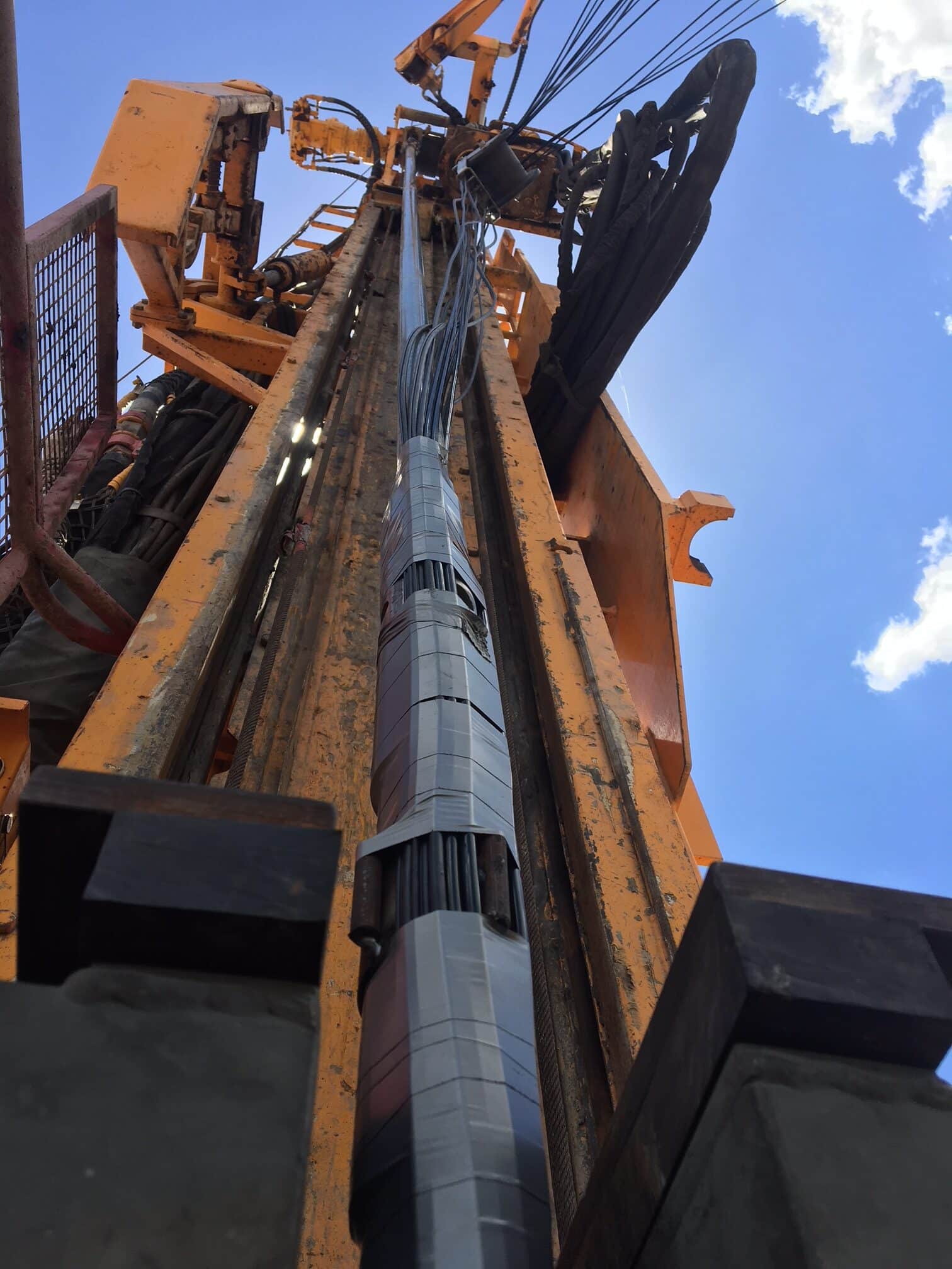
The grout strings that Sigra use for greatest installation reliability comprise steel tubing designed and manufactured by Sigra, as shown in Figure 4 they provide three distinct advantages over other installation methods. Firstly, the steel tube provides precise position of the piezometers downhole. Secondly, protective fins on the steel pipe protect cables from sliding damage during installation. Thirdly the stiff steel tube allows for installation through drill pipe, to guarantee successful placement of the piezometer string in even the most unstable hole conditions. Figure 5 shows the steel tube and cables going into a borehole with cable protection by steel spacers.
Sigra can also install a combination of steel tubing with fibreglass or brass pipe through areas that may be mined, such as coal seams.
Polyethylene pipe may be used on some shallower installations as a low cost option, but it lacks the robustness of the steel option.
Cable Sealing – Gas Wells
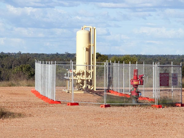
Where gas wells are being monitored, Sigra can design the piezometer installation to ensure there is no gas leakage to surface by using the appropriate data cable, low shrinkage grouts with a high density, and suitable sealing systems at surface.
Uses for Cement Grouted Piezometers
Sigra’s cement grouted system may be used in deep aquifers, coal seam gas reservoirs or in soils. The cement grout installation system is fully described by Gray and Neels 2015.
Cemented Tube Systems – Precision Aquifer Monitoring
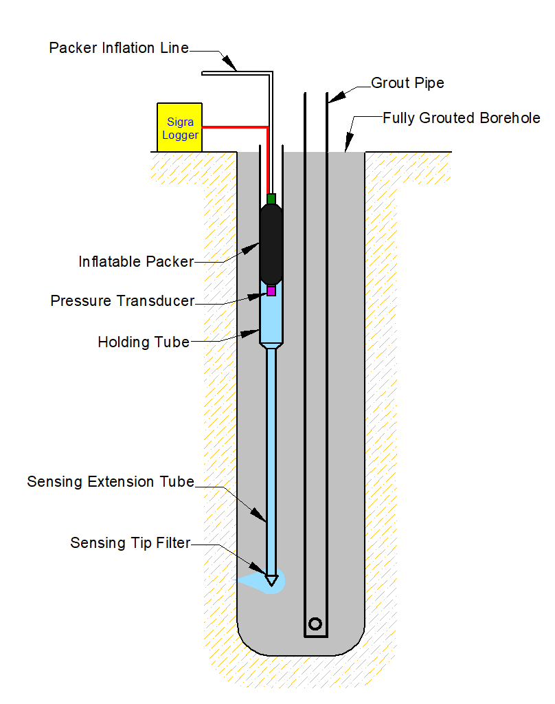
This system involves attaching a small diameter nylon or stainless steel sensing tube to the grout pipe. In the upper zone of the borehole this is connected to a pipe of 20 mm bore. This tube is water filled and sealed. The borehole is then grouted and connection made between the sensing tube tip and the formation by cement displacement brought about by pumping high pressure water through the sensing tube. This is undertaken before the cement grout has fully set so as to displace the cement. Further injection of water after the cement has set can be used to confirm the connection between the monitoring tube tip and the formation. A pressure transducer is then lowered to a suitable monitoring depth in the pipe and sealed in place with a packer. Provided the packer is set below the water table it eliminates the problems associated with fluid volume changes that occur in standpipe type installations. This technique is particularly suitable for monitoring aquifers with high water tables to a very high degree of accuracy. It also permits the pressure transducer to be removed for replacement or to move its location within the tube as pressures change. It is not suitable where mixed gas and water phases exist.
Figure 6 shows schematically a cemented tube system. The Sensing extension tube and holding tube are cemented into the borehole. As the cement becomes plastic it is displaced with water to connect it with the formation. An inflatable packer with pressure transducer on the bottom is then lowered into the holding tube. Once the packer is inflated the pressure transducer will read the formation pressure at the sensing filter tip.
Multi Packer Systems
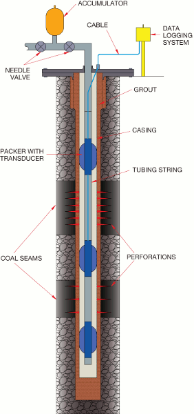
Sigra manufactures and supplies inflatable multi-level packer and piezometer systems for use in cased and perforated boreholes. A production hole may be converted to a monitoring well prior to its use in production. Figure 7 shows schematically such an installation.
Swell Packer Systems
In cases where the rock mass is essentially impervious but has specific fracture sets which contain fluid, the best method to permit monitoring has been found to be the use of swell packers where the water or other fluid in the borehole causes the packer to swell sealing the hole. These are used to straddle the relevant fractures thus enabling the pressure within them to be monitored using a suitable pressure transducer.
Well Control During an Installation
To install any piezometer system, Sigra must inherit a well that is under control. This means it is not flowing uncontrollably. It will then maintain well control throughout the installation process. This can be accomplished by control of mud and grout in the well. Sigra can, in addition, install blow out preventers if required.
Intrinsic Safety and Hazardous Zones
Sigra has found that clients have differing policies with respect to hazardous zones and the use of intrinsically safe equipment.
Sigra can meet any standard, however we have adopted some practices which most groups find acceptable. These are:
Cables Used in Piezometer Installations
Sigra can supply and install a variety of cables in its piezometer systems. Where pressure transducers are to be cement grouted in place, the risk of cable damage leading to total system failure is increased, so Sigra recommends separate cables to each pressure transducer. All the cables Sigra provide are fully filled with gel or plastic to eliminate leakage through the cable.
The most generally used cable types are:
Pressure Transducers for Piezometer Installations
Sigra can supply a range of pressure transducers for downhole use. The product range comprises devices that produce a digital output rather than either current loop or bridge outputs as the latter two are susceptible to drift. Sigra uses pressure transducers with a frequency output or a digitized signal. All pressure transducers are calibrated against traceable standards for pressure and temperature effects. The available pressure transducers are:
Quartz frequency based transducers: These devices represent the top end of precision and would seldom be cemented into a well because of their cost. The accuracy is about 0.02% of full scale (The minimum full scale pressure is 35 MPa).
Vibrating Wire Transducers: These are the civil engineering industry standard for stability (virtually zero drift) and simplicity. They are available in various temperature ratings. The standard form of these is suitable to 80oC but can be obtained in ratings up to 230oC. The accuracy of these transducers is about 0.2% of full scale following calibration by Sigra. However the sensitivity can be brought down to 0.003% using Sigra’s highly sensitive field data logger.
Production Well Monitoring Systems
Sigra supplies transducers for use in production gas wells. These are digital devices usually supplied with armoured cable to surface.
Underground Pressure Monitoring
Sigra manufactures and uses packer systems for monitoring pressure changes underground. An example of this is shown schematically in Figure 8. This is the underground analogue of the system shown in Figure 7.

It also cements in permanent pressure sensing points using cement displacement. Such a system is shown schematically in Figure 9. This is the underground analogue of the system shown in Figure 1.

Simple Piezometer Installations
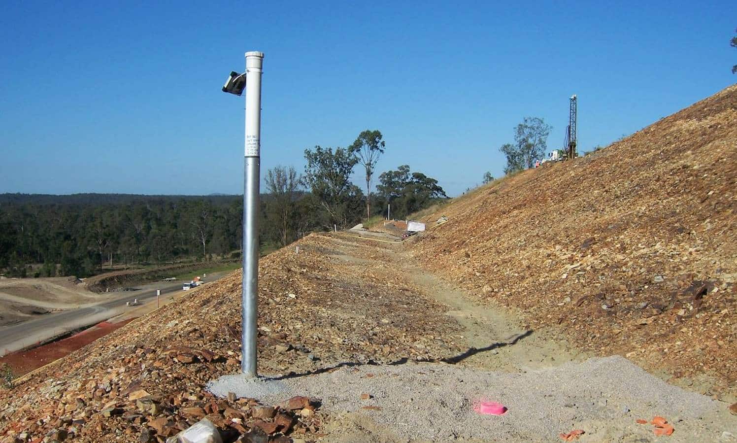
Sometimes the old fashioned piezometer systems work best. In highly fractured rock or high permeability soils with an unconfined water surface it is generally best to still use a standpipe installation with a filter tip surrounded by sand and gravel and sealed with bentonite against water ingress. The monitoring of these may be automated by placing a pressure transducer in the standpipe. Figure 10 shows such an installation.
