Sigra undertakes permeability testing using its drill stem test tools. These are used in drill stem test (DST) mode to produce fluid from the formation being tested into a partially emptied drill string or, alternatively, to inject fluid. Drill stem testing generally produces the most reliable permeability information as it reduces problems with well bore damage and the injection of drilling mud and particulate matter into the reservoir being tested.
The tools were originally designed for measuring permeability in coal seam reservoirs but are also ideally suited for use in groundwater testing.
Tools
Sigra operates two types of DST tool for permeability measurement, a through-the-bit system and an end-of-string system.
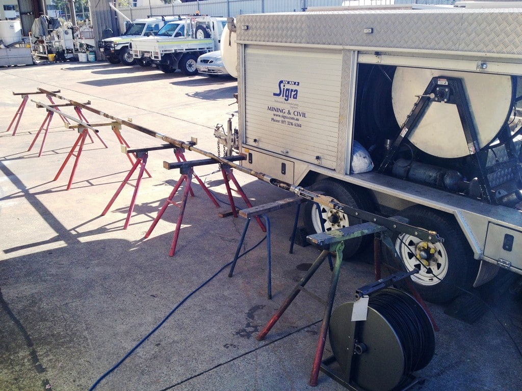
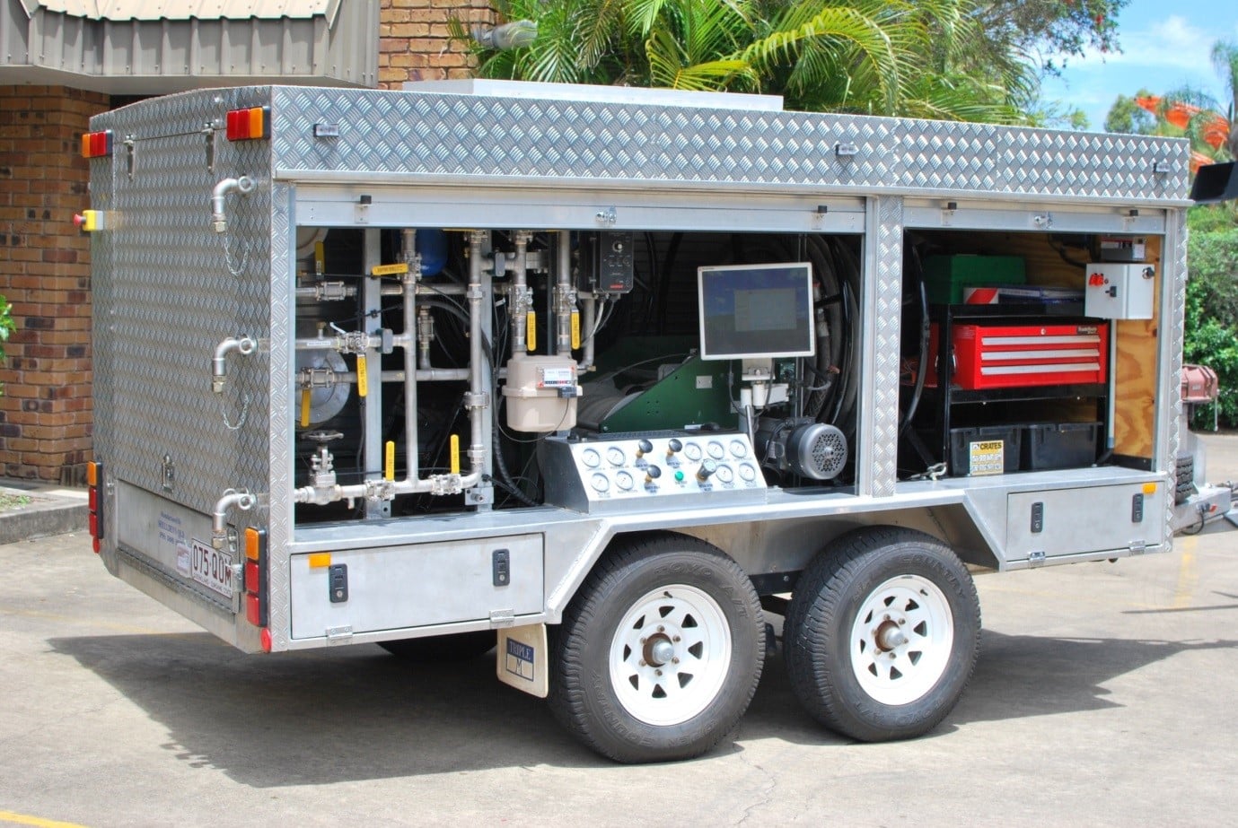
The most commonly used tool is the Through-The-Bit Drill Stem Test tool (TTBDST) which may be used in either bottom test or straddle mode. This tool is run on wireline through the HQ or HRQ drill pipes and out of the core bit. This tool removes the need to trip pipes between tests. Due to the slim nature of the tool, the borehole diameter where the packer’s seat must not exceed 105 mm. If it is used in testing after the hole is completed, calliper logging is recommended prior to testing to reduce risks of setting packers into a washout. The DST trailer and Through-The-Bit Drill Stem Test tool are shown in Figure 1. Figure 2 shows the trailer from the control side.
The operation of the through the bit DST tool is shown in Figure 3.
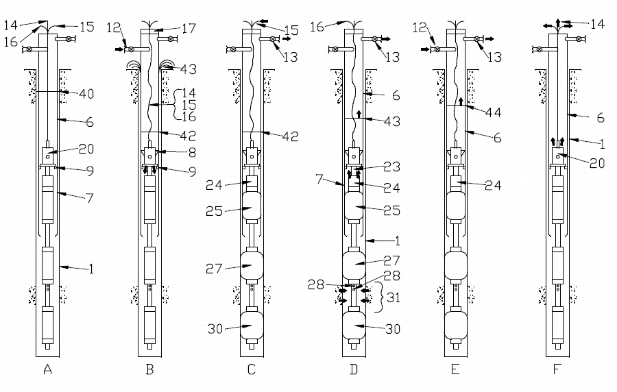
A. The wireline DST tool is lowered through the HQ drill string.
B. The DST tool is shown landed and locked into the core barrel.
a. A head seal is placed at the top of the drill pipe.
b. Compressed air is used to push down the water level in the drill string.
C. The packers are inflated.
a. Compressed air is bled off.
b. The test zone is allowed to come to equilibrium.
D. The valve is opened so inflow can take place.
E. The valve is closed so that a head build up can take place.
F. The packers are deflated and the tool can be pulled out of the hole.
Sigra also have a closed chamber Through-The-Bit Drill Stem Test Tool (CCDST). This is designed for use with a 6 m HQ core barrel. As the chamber volume is 9 litres, it is suitable for lower transmissivity (permeability x thickness) reservoirs. A major advantage of this tool is that it does not require a compressor to depress the liquid head in the drill pipe.
In circumstances where testing must be conducted on zones of diameter greater than 105 mm, Sigra has DST tools with larger packers that are attached to the end of the drill string. These require the drill string to be pulled out to attach the tools. Once fitted, the tools may be used repeatedly without tripping if the straddle distance can be kept constant.
All of Sigra’s tools operate using a wireline to conduct information to surface. A flexible inflation tube may also be used in some of the tools. The tools are designed for operation with HQ or HRQ drill string (88.9 mm OD, 77.8 mm ID). The end of string tools may be used with any drill string with tool joints that have an internal diameter greater than 63.5 mm.
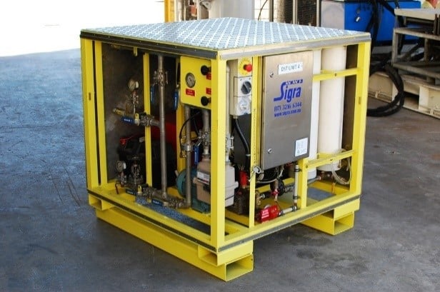
The DST equipment is conveyed to site in a trailer or in a pod. This houses the electronics, reels, pumps and flowmeters required for an operation. A snubber is also carried to shut in the test string in the event of packer failure.
Test Time
Permeability tests take as long as the reservoir demands to provide a solution. Failure to take tests to completion leads to their being unanalysable. Sigra staff have real time displays of the reservoir behaviour. This permits them to determine when the test has reached a stable state and can be analysed.
In high permeability cases, the tests may be completed in a few hours. In medium to low permeability cases, the recovery part of the test is frequently conducted overnight. In very low permeability reservoirs, the tests may need to be run over two days. It is not normal practice to conduct DST tests for longer than this.
Analysis
Most well analysis procedure is based on a single phase and the use of graphical techniques. The analysis procedure used here is based upon the use of the Horner plot (a plot of pressure vs. the Horner time function). This becomes linear at some time after shut in. To choose this period of linearity, a plot of the derivative of the pressure change with respect to the natural log of Agarwal equivalent time is used. This plot produces a straight horizontal line at the time of established radial flow. The Agarwal equivalent time is given in equation (1).

Analysis is generally on the basis of a single phase which may generally be a liquid (water) but may also be gas. It is also possible to assess the permeability to each phase from a test that flows both phases. In addition to the permeability, the reservoir pressure is assessed and the well bore loss terms described. The well bore loss terms are evaluated in terms of skin factor (a measurement of near well bore loss) and effective well bore radius. The skin factor is considered at each stage of the inflow period.
In reality very few drill stem tests produce a uniform flow rate and the analysis is derived on the basis of multiple flow rates using the principals of superposition.
The mean effective radius of investigation is also calculated. It is based on the actual times of the points used in determining the slope of the Horner plot and represents the mean radius at which the pressure changes between these times may be considered to act.
Sigra may additionally analyse the early part following shut in for pressure dependent permeability.
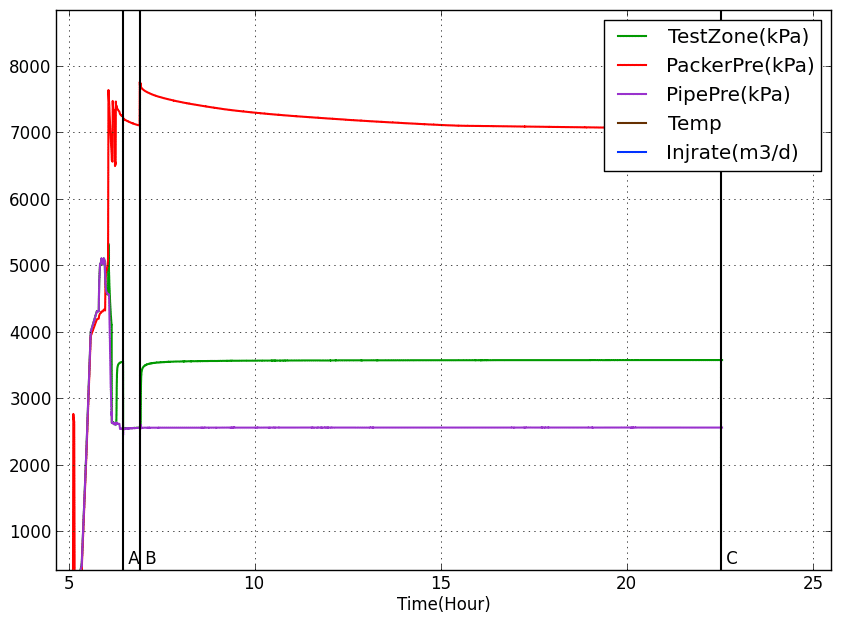
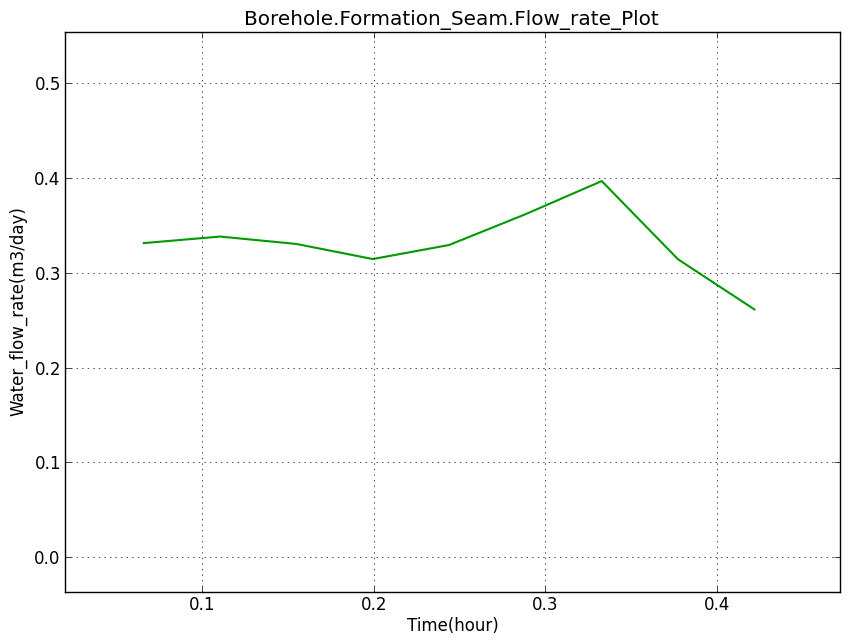
Figure 4 to Figure 8 show a typical DST test. Figure 4 shows the full test showing a short pre-flow followed by a shut in and then the main inflow period. This is followed by a shut in and build up. Figure 5 shows the analysed inflow rate during the main inflow period. Figure 6 shows the pressure change from shut in and its derivative with respect to Agarwal time. Figure 7 shows the Horner build up plot and its analytical period while Figure 8 shows the skin factor variation during the inflow period.


Sigra also have smaller portable DST systems for use of the back of truck or a utility (pickup or bakkie). These are shown in Figure 9 and Figure 10.

Sigra’s Requirements for DST or Injection Fall Off Testing
To conduct permeability tests, Sigra require access to:


