Sigra undertakes rock stress measurement in boreholes using its IST overcore system, which is suitable for holes up to 2000 m depth. It also undertakes hydrofracturing for stress measurement and analyses borehole breakout data.
As fluid pressure is a component of effective stress, Sigra has a number of techniques for measuring fluid pressure in rock.
In addition, Sigra has the capability to measure stress changes using a variety of systems which are designed to be cemented into boreholes.
Sigra also conducts surface stress measurement to determine the state of stress on the walls of excavations. This is sometimes more useful than measuring stress remotely as it gives the stress value where it matters.
Sigra In-situ Stress Testing (IST) by Overcoring System
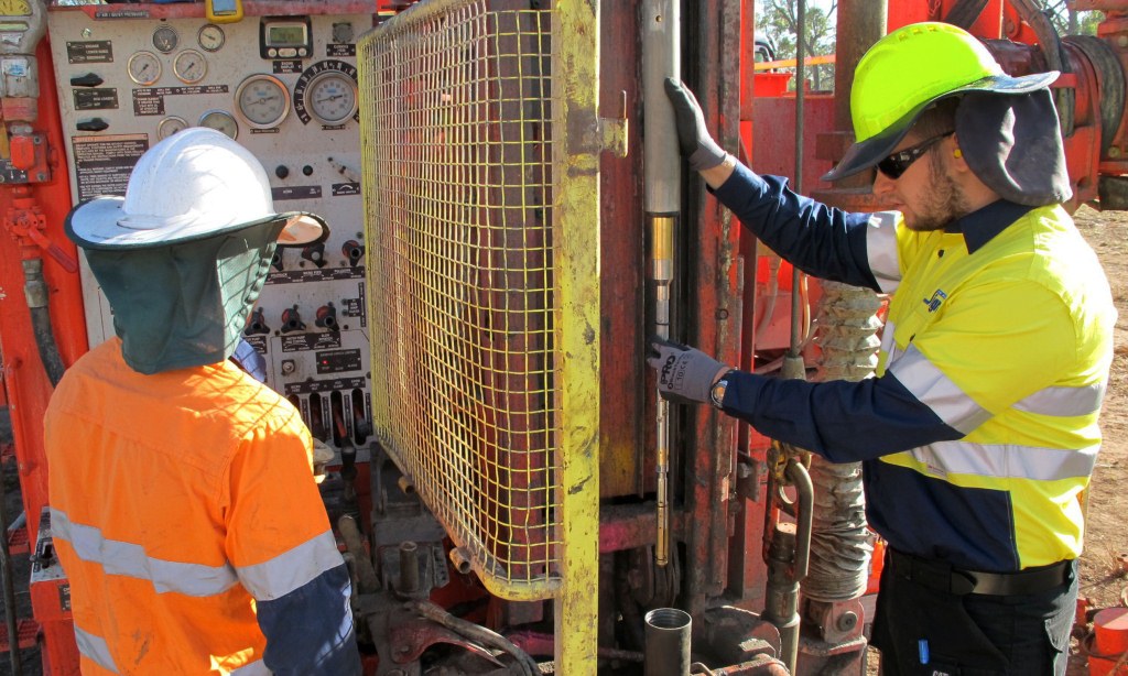
Sigra measures in-situ rock stress primarily by the use of its IST tool. This is an overcore device which operates in conjunction with the Boart Longyear HQ wireline coring system and permits stresses to be measured at up to 2000 m depth.
The tool is a re-usable device which returns high quality two dimensional stress information quickly, where the rock stress is not high enough to cause rock breakage of the pilot hole. Most Australian coal mines have used the Sigra IST system as part of their exploration programmes.
The Sigra in-situ stress (IST) measurement technique is designed to provide the best possible combination of desirable features. In essence, the tool is similar to the United States Bureau of Mines borehole deformation gauge (Merrill, 1967) in that it is a biaxial deformation device used to measure the change in diameter of a pilot hole.
The advantages of the IST tool are that it is smaller, measures six diameters of the pilot hole, and does not use a cable for communication. This means that the use of tool is not restricted by depth. It has been used in measurements to 1 km in depth and can be used to 2 km. The overcore system is primarily set up to be used as part of a Boart Longyear HQ wireline coring system.
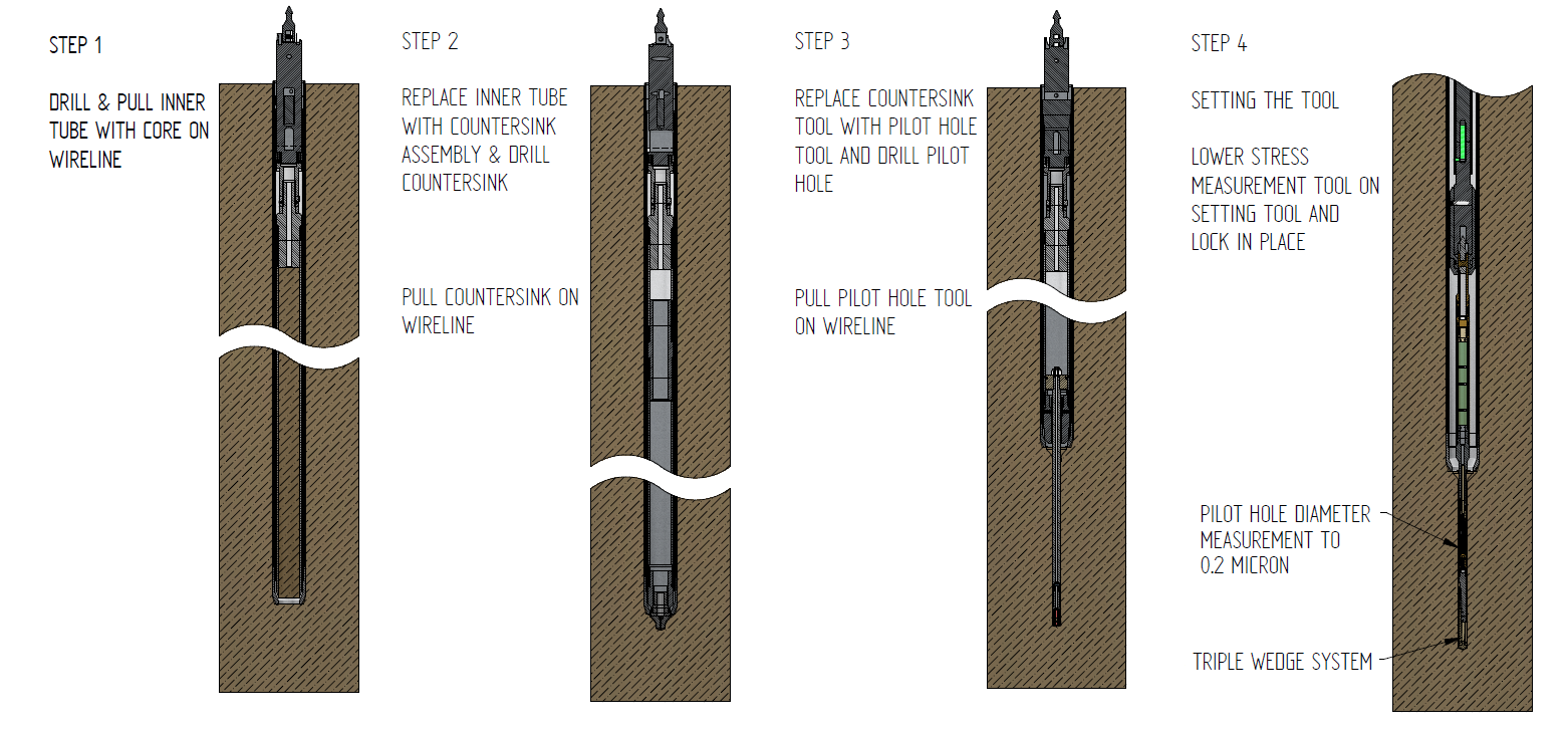
The process is outlined in Figure 1. It involves pulling the core, then in place of the inner barrel a stump grinding and countersinking bit is run and used to remove any upstanding core stump and centralise hole for the subsequent pilot hole. This is withdrawn and a pilot hole drill is used to create a hole 500 mm long and 25.5 – 26.5 mm in diameter. The pilot hole drill is withdrawn on wireline and the tool lowered into the hole where it locks into place. The rods are pulled back so that the onboard orientation tools can detect the location of the tool free from magnetic interference. The core barrel is then pumped into the rods and coring commences.
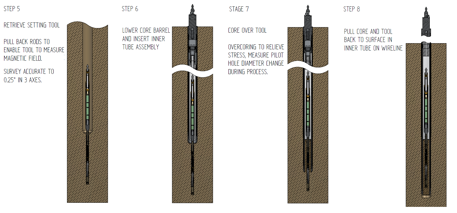
During the overcoring operation a record of diameter change is obtained and stored electronically. Once coring has been completed, the core containing the tool is pulled. The diameter measurements and those taken from the accelerometers and magnetometers are downloaded. The core is tested for Young’s modulus and Poisson’s Ratio and the results are used with the deformation information to arrive at the biaxial stress field perpendicular to the borehole.
Because the orientation of the tool is measured, the direction of the principal stresses can be found.
The tool is a biaxial device and if testing is only conducted in a single borehole an assumption must be made as to the stress in the axial direction of the hole. As the tool is normally used in vertical drilling from surface the assumption is usually that the vertical stress is that of overburden weight.
Where this has the most limitation is within zones where reverse faulting leads to areas of increased vertical stress and adjacent zones of reduced stress. Because of the biaxial nature of the measurement process, it is not possible to deduce any shear components of stress that are not perpendicular to the borehole.
Despite these limitations, the ability to perform a stress measurement at 800 m depth in about 3 hours, and to be able to examine the overcore trace directly on retrieval of the tool along with the core, provide very significant advantages compared to other systems.
The steps in the stress measurement process using the IST are:
- Drilling the hole
- Pulling core by wireline
- Pumping in a countersink tool
- Grinding the core stump
- Pulling the countersink tool by wireline
- Pumping in the pilot hole tool
- Drilling a pilot hole
- Pulling the pilot hole drill by wireline
- Running the IST tool into the hole on a setting tool on wireline
- Pulling the setting tool on wireline while leaving the stress tool locked in place
- Pulling the drill string back so that the IST tool magnetometers are not influenced by the magnetic effects of the core barrel
- Waiting for magnetometer and accelerometer data to be recorded
- Lowering the core barrel back over the IST tool
- Coring over the IST tool while it records changes in diameter
- Pulling the core containing the IST tool to surface by wireline
- Downloading the tool of data gathered during the process
- Checking the borehole deformation profile of the hole as measured by the six pin sets of the tool
- Testing the core for Young’s modulus and Poisson’s ratio
- Calculating the horizontal stresses and their orientation based upon the hole deformation and elastic parameters and orientating the results based upon the magnetic and gravitational field measured by the tool.
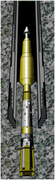
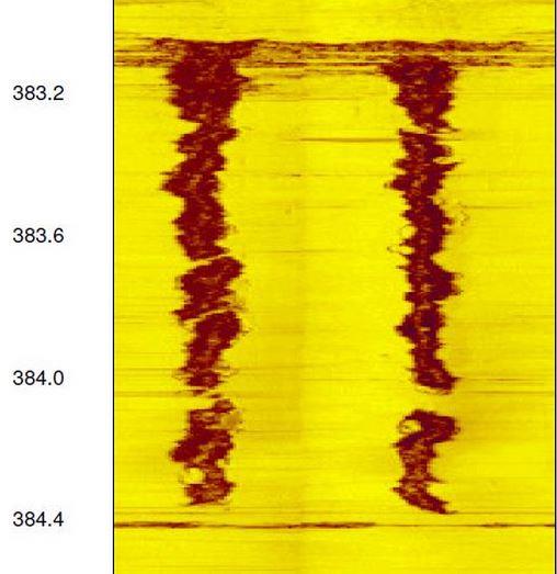
A pictorial view of the overcore is shown in Figure 2. The overcore traces can be viewed as soon as the tool is brought to surface and downloaded and an analysis can be conducted based upon estimated elastic parameters.
Sometimes a reasonable solution can be obtained even if minor breakout affects no more than two pin sets. A typical stress measurement operation at 500 m depth interrupts coring by 2 ½ hours. Deeper tests take longer because of the time involved in running the tools up and down the borehole.
The overcoring process is shown in Fig. 2 while examples of the diameter traces during the overcore are shown in Fig. 3. Fig. 4 shows the best fit of a theoretical pilot hole deformation to the measured deformations.
These tools have been in successful use in some 2000 stress measurements made at depths up to 800 m mostly over the coal and gas field areas of eastern Australia but also in the USA and South Africa.
In these areas the diameter change to the 26 mm pilot hole lies typically in a range of 0.005 to 0.25 mm. The tool reads to about 0.0005 mm accuracy. Hard rocks have also been the subject of the use of the tool. Notable in these was the testing of ignimbrite at the site of the Burdekin dam in North Queensland. Here a major stress of 30 MPa was repeatably determined in rock of 350 MPa UCS with a Young’s modulus of 80 GPa.


The prime limitations of the technique are, from a practical viewpoint, the smoothness of the drilling and the evenness of the pump pressure used while drilling. Excessive vibration causes problems with measurement as does pulsating drilling fluid, as this loads the pilot hole. These issues are generally managed by proper drilling technique to provide successful measurements.
Theoretically, the most complex problem is dealing with non-linearly elastic rocks, as are moderately frequently encountered in sedimentary rock. Generally Sigra uses the unloading modulus from a uniaxial test. However where there is any reason to believe that significant anisotropy exists, the core can be tested with axial and radial stress. This is done in a stepwise manner using the unloading behaviour.
The analysis takes account of the effects of stress relief due to the overcore process and the effects of fluid pressure within the hole.
Download Sigra’s IST By Overcoring Brochure here
Hydrofracturing
Where holes have already been drilled, Sigra can use its hydrofracturing system to determine the rock stress regime. This provides values of major and minor principal stresses even in cases where tensile stresses exist at the wall of the test hole. The system can be regarded as providing a lesser level of accuracy than the overcoring via the Sigra IST system and at a greater cost. However in fractured ground it is the only way to gain an indication of stress across joints.
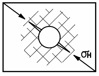
Practically, hydrofracture is a biaxial technique. The solution of the stress field perpendicular to a borehole also requires material that has not failed and behaves in a linear elastic manner. This measurement also requires that the borehole is uncased and assumes that a failure will occur parallel to the hole axis in the direction of minimum stress.
In fact to achieve a pressure seal in an open hole, packers must be at a higher pressure than the fluid being injected and therefore they will initiate failure unless some pre-existing rock fracture exists in the test zone.
If the rock stresses are sufficiently anisotropic it is possible that a tensile zone and associated fracture exist parallel to the borehole wall prior to the fluid pressure being raised. This axial fracture will compromise borehole sealing and makes analysis more complex.
In the event that the minimum stress is perpendicular to the borehole most packer systems will not permit loading of the rock in the axis of the hole because the packers are mechanically linked and the initial fracture will be parallel to the hole. After initiation the fracture will roll over into a plane which is perpendicular to the minimum stress.
This also complicates analysis as the closure pressure analysed is not the intermediate stress perpendicular to the hole. In the instance where a pre-existing fracture exists transecting the hole, then fluid pressure may act on its faces and jack the fracture open.
Where borehole wall failure occurs prior to fracturing it compromises any seal and causes a deviation from the theoretical equations of stress at a borehole wall. In this case it is still possible to get a closure pressure following hydrofracturing which represents the minimum stress. This is the process generally used in the oilfield to establish a (minimum) stress.
Another problem with hydrofracture stress measurement in an open hole is that the pressure that the packers exert on the borehole wall must exceed the fluid pressure. The force they exert will therefore tend to initiate failure separate to the hydrofracture fluid.
In summary, the use of hydrofracture as a stress measurement technique is fraught with practical and analytical problems. It can still be a useful second choice to measure stress, especially in hard rock where the deformations due to overcoring are very small, or if a minimum stress is all that is sought. In the latter case this can be achieved through a cemented casing.
Surface Stress Measurement
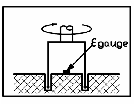
While the above three techniques are for measuring stress at depth, Sigra also undertakes surface and near surface stress measurements. These involve strain-gauging the wall of a tunnel or mine opening and overcoring using a concrete coring system, so as to relieve the stress around the strain gauge.
This technique has been used in excavations and within tunnels. The most notable of these is the Bogong Power project in the Snowy Mountains, where four surface stresses were measured around the periphery of a circular tunnel created by a tunnel boring machine in granodiorite. These surface stress values permitted the calculation of the overall far field stress. We believe that this tunnel was the world’s largest overcore pilot hole!
The surface stress is frequently a more important measurement than the virgin stress at depth as, combined with rock strength, it provides an immediate estimate of the opening stability.
Breakout Analysis
Borehole Breakout
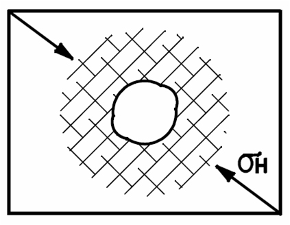
Borehole breakout provides another method of assessing biaxial stress distribution around a hole. The method of measurement here is the failure of the borehole and this is measured by an acoustic scanner. If the wall stresses are insufficient to induce compressive failure of the borehole wall, then no indication of the stress field may be made. Alone, the acoustic measurement of breakout only permits the direction of major stress perpendicular to a borehole to be estimated.
If the angular width of the breakout is measured, there is a basis for knowing the minimum stress and in addition if there is a good knowledge of the material strength where the breakout has occurred, then the maximum stress perpendicular to the hole may be calculated.
Thus if core has been taken from the hole at the location of breakout for uniaxial compressive strength (UCS) testing and the closure pressure from hydrofracture is also known, then there is a basis for calculating the maximum stress perpendicular to the hole.
Doing this requires good information on the rock strength.
For example, trying to establish a UCS by correlation from a sonic log would usually not provide an adequately accurate value for use in calculating stress from breakout. What is really required is a UCS measurement transverse to the hole.
Stress Change Measurement
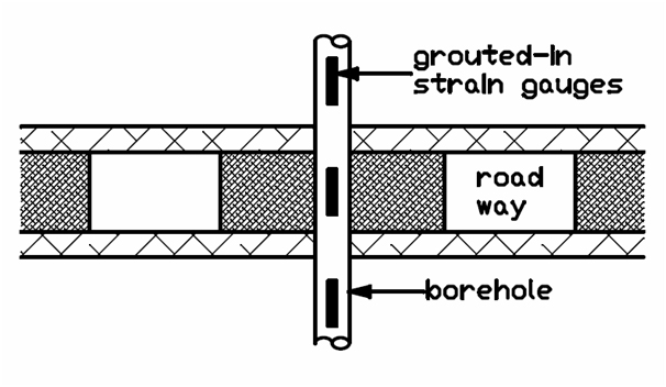
Sigra has the capability to measure stress change. This can be by installing and monitoring surface or near-surface strain gauges, or by cementing stress change cells in boreholes. The cementing process can be accomplished at great depth. Sigra has supplied and installed equipment to measure stress changes associated with dewatering and degassing of coal seams, and to monitor the changing stresses around a fault in a longwall.
Both these installations used a stress change cell cemented at several hundred metres depth in a vertical borehole. The cementitious grout used in the installation expands following its initial set so as to pre-load the stress change cell and permit it to measure stress relaxation.
Normally stress change devices would be installed in a hole where the initial state of stress has been determined by a stress measurement such as that through the Sigra IST system.
The stress change installations take three forms: uniaxial, biaxial+axial, and fully triaxial.

Uniaxial Stress Change
These installations involve cementing an axially strain gauged tube into a borehole and measuring the strain change and relating it to the in-situ stress change through the Young’s modulus and Poisson’s ratio of the surrounding rock. The prime use of the method is in determining pillar stress strain relations. Here the process is to cement axial stress change cells in the roof, pillar and floor. The roof and floor stress change cells yield a measurement of the stress and therefore load on the pillar, while the pillar gauge provides a strain measurement beyond the elastic range.
The load strain characteristics of the pillar may therefore be deduced from these measurements. These devices use vibrating wire strain gauges.
Biaxial + Axial Stress Change
These are a development of the uniaxial gauge and have in addition to the axial vibrating wire strain gauge, four transverse strain gauges. These enable the state of stress in the plane perpendicular to the gauge to be determined and therefore a more complete picture of stress to be determined.
Once again the determination of the state of stress is dependent on knowing the elastic properties of the rock in which the gauge is installed. These may be quite anisotropic in which case Sigra’s system for determining the triaxial modulus should be used.
Fully Triaxial Stress Change
These also consist of a tube which is cemented into a borehole with an expanding cementitious grout. These are however fitted with electric resistance strain gauges and down hole amplifiers and A to D converters. These devices enable the fully triaxial state of stress change in rock to be determined.
Fluid Pressure
Fluid Pressure Measurement
The measurement of fluid pressure in rock is an essential part of determining the effective stress regime that exists.
To enable this Sigra has various techniques for measuring fluid pressure in rocks. These involve the use of grouted-in pressure sensing points (with or without transducers) and the use of packer based systems for zone isolation in pressure measurement.
These techniques can be used in boreholes drilled from surface or underground.
Click here for further information on pressure sensing equipment.